

Updated for 2025 | Civil Engineering | JKSSB JE, SSC JE, RRB NTPC
📌 Introduction
In Strength of Materials (SOM), the Shear Force Diagram (SFD) and Bending Moment Diagram (BMD) are fundamental analytical tools used to visualize the internal forces and bending moments that develop in a beam under various types of loading, such as point loads, uniformly distributed loads (UDL), and varying loads.
These diagrams not only help engineers identify weak points or maximum stress locations in a beam but also allow them to determine the magnitude and distribution of shear force and bending moment at every section along its length. Understanding SFD and BMD is critical for structural safety, economical design, and selection of appropriate beam cross-sections for civil engineering projects.
In JKSSB JE Civil Engineering exams, SFD and BMD often appear as:
- Direct theory questions (definitions, shapes, sign conventions).
- Numerical problems (finding maximum shear and bending moments).
- Interpretation questions (reading diagrams to find load type).
🎯 Learning Outcomes from this Topic
After studying this guide, you should be able to:
- Understand Shear Force and Bending Moment concepts.
- Apply sign conventions correctly.
- Draw SFD and BMD for common loading cases.
- Calculate maximum bending moment & shear force for design.
- Solve exam-type problems quickly.
🧠 Understanding the Concepts
1️⃣ Shear Force (SF)
Definition:
The algebraic sum of all vertical forces (including applied loads and support reactions) acting on one side of a chosen section of a beam, which determines the shear force at that section. This value can be positive or negative depending on the direction of the forces, and is a key parameter for drawing the Shear Force Diagram (SFD).

where V is the vertical load component.
Physical meaning: Shear force tends to cause sliding of one part of a beam over another.
2️⃣ Bending Moment (BM)
Definition:
The algebraic sum of the moments of all forces (including point loads, distributed loads, and reactions) acting on one side of a chosen section of a beam, taken about that section. This represents the bending moment at that specific point, which can be positive (sagging) or negative (hogging) depending on the nature of the bending, and is essential for constructing the Bending Moment Diagram (BMD).

Physical meaning: Bending moment causes bending or flexure in the beam.
📏 Sign Conventions in SFD & BMD
Shear Force:
- Positive (+) → Load acting downward to the left of the section OR upward to the right of the section.
- Negative (-) → Opposite of above.
Bending Moment:
- Positive (+) (Sagging) → Beam curves upward at the center.
- Negative (-) (Hogging) → Beam curves downward at the center.
📜 Common Loading Cases – Formulas & Diagram Shapes
| Case | Shear Force (SFD) | Bending Moment (BMD) |
|---|---|---|
| Cantilever with point load at free end | Constant (horizontal line) | Linear (sloped line) |
| Cantilever with UDL | Linear slope | Parabolic curve |
| Simply supported with point load at center | Step change at load | Symmetric triangle |
| Simply supported with UDL | Linear slope | Parabolic curve |
| Overhanging beam with point load | Step change + slope | Linear + triangular |
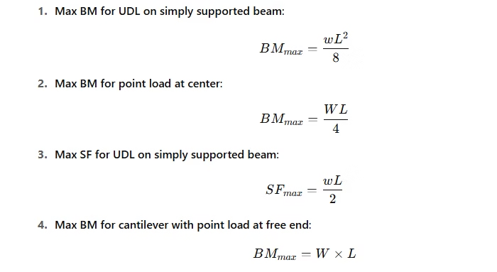
📊 Formulas for Quick Calculation
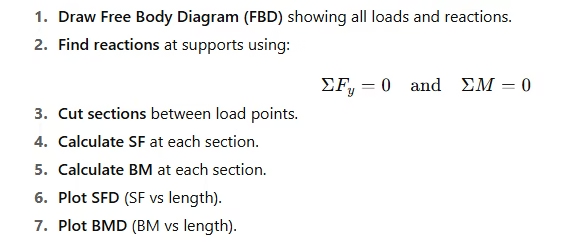
📚 Step-by-Step Method to Draw SFD & BMD
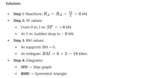
🛠 Numerical Example 1
Q: A simply supported beam of span 6 m carries a point load of 12 kN at midspan. Draw SFD & BMD.
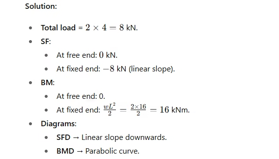
🛠 Numerical Example 2
Q: A cantilever of length 4 m carries a UDL of 2 kN/m. Draw SFD & BMD.
Solution:
💡 Tips for JKSSB Exam
- SFD slope is equal to the intensity of load (w).
- BMD slope is equal to shear force.
- At a point load: SF changes abruptly, BM is continuous.
- At a point moment: BM changes abruptly, SF remains unchanged.
- Zero shear force location → Point of maximum/minimum bending moment.
📌 Conclusion
Mastering SFD and BMD not only boosts performance in JKSSB Civil Engineering exams but also equips you for real-world structural design and analysis tasks, where accurate load calculations and safety checks are crucial.
For exam preparation, practice standard cases repeatedly, memorize key formulas for shear force and bending moment, and learn to quickly recognize diagram shapes for common load configurations. In fieldwork, this knowledge translates to faster problem-solving, better communication with design teams, and the ability to verify structural safety on-site.
Frequently Asked Questions (FAQs)
Q1. What is the purpose of a Shear Force Diagram (SFD)?
A. It represents how shear force varies along the length of a beam, helping to locate maximum shear force points and design for safety.
Q2. What is the purpose of a Bending Moment Diagram (BMD)?
A. It shows how bending moment changes along the beam, helping identify maximum bending points for structural design.
Q3. What are the common sign conventions in SFD and BMD?
A. Positive shear force causes clockwise rotation of the section, and positive bending moment causes sagging. Negative values imply opposite effects.
Q4. What is the relationship between load, shear force, and bending moment?
A. The slope of the SFD at a point equals the load intensity, and the slope of the BMD at a point equals the shear force.
Q5. Can SFD or BMD be non-linear?
A. Yes, under non-uniformly distributed loads, BMD can be parabolic or cubic, and SFD can be sloped.
Q6. Why do JKSSB exams focus on SFD and BMD?
A. Because these concepts form the foundation for beam design and analysis, which is vital in civil engineering practice.
Previous Year Questions (PYQs) – JKSSB & Other Exams
Q1. A simply supported beam of span 6 m carries a UDL of 10 kN/m. What is the maximum bending moment?
Answer: 45 kNm
Explanation: Maximum BM for simply supported beam under UDL = (wL²)/8 = (10×6²)/8 = 45 kNm.
Q2. For a cantilever beam with point load P at free end, the SFD is:
Answer: A rectangle of magnitude P along the span.
Explanation: Shear is constant along the length for point load at free end.
Q3. The bending moment at the free end of a cantilever is:
Answer: Zero.
Explanation: Bending moment is maximum at the fixed end and zero at the free end.
Q4. The point where bending moment changes sign is called:
Answer: Point of contraflexure.
Explanation: At this point, the beam changes from sagging to hogging.
Q5. In a simply supported beam with central point load, the maximum shear force occurs at:
Answer: Supports.
Explanation: Shear force is maximum at the supports and decreases towards the center.
Q6. The SFD for a simply supported beam under UDL is:
Answer: A straight sloping line.
Explanation: Shear decreases linearly under UDL.
📌 Join our Telegram Channel JKSSB CivilsCentral for regular updates, quizzes, PDF notes, and practice sets curated specifically for JKSSB aspirants.